


| Product Family and General Specifications | ||||||||||||
| This series includes various shells from XT1 to XT7, and their core features are compared below: | ||||||||||||
| Model | Frame current (A) | Extreme number | Rated operating voltage Ue (AC) | Maximum splitting capacity (415V) | Rated insulation voltage Ui (V) | Rated impact withstand voltage Uimp (kV) | Core positioning and application scenarios | |||||
| XT1 | 160 | 3/4 | 690V | 50kA | 800V | 8 | Compact type: Standard power distribution protection suitable for residential and commercial buildings. | |||||
| XT2 | 160 | 3/4 | 690V | 150kA | 800V | 8 | High-performance type: Breaking capacity up to 200kA, supports various electronic trip units, suitable for advanced power distribution and motor protection. | |||||
| XT3 | 250 | 3/4 | 690V | 36kA | 800V | 8 | Reliability type: Selection of 250A-class industrial standard power distribution | |||||
| XT4 | 250 | 3/4 | 690V / 750V DC | 150kA | 1000V | 8 | Enhanced version: Integrated with electricity metering function, suitable for applications requiring monitoring and communication. | |||||
| XT5 | 400 | 3/4 | 690V | 150kA | —— | —— | Fill the demand between 160A and 400A | |||||
| XT6 | 630/800 | 3/4 | 690V | 70kA | —— | —— | Suitable for high current distribution networks of 630A-800A | |||||
| XT7 | 1000-1600 | 3/4 | 690V | 150kA | —— | —— | Maximum frame size, used for main power distribution below 1600A. | |||||
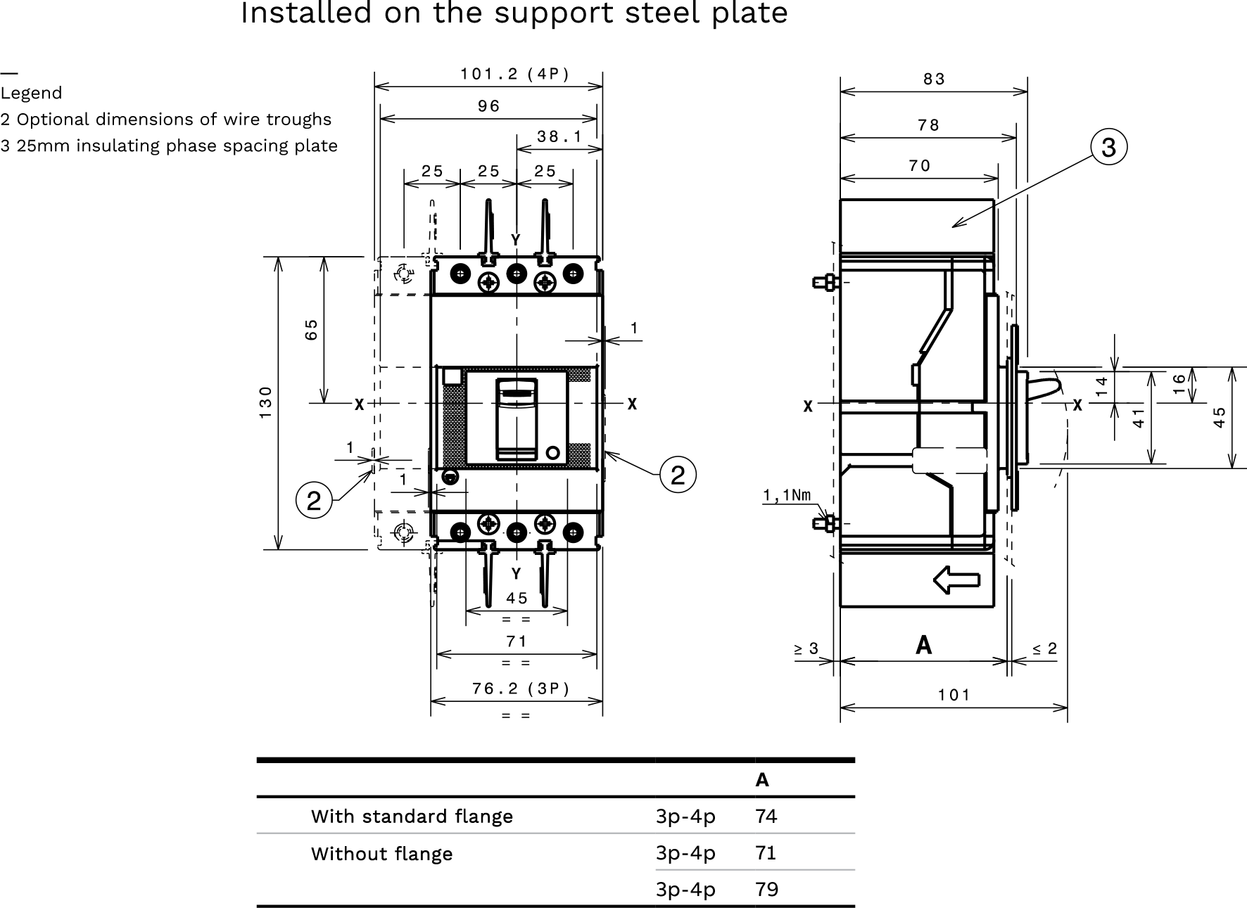
Dimensions
| Tmax XT1 - Installation |
| Installation of Fixed Circuit Breakers |
 |
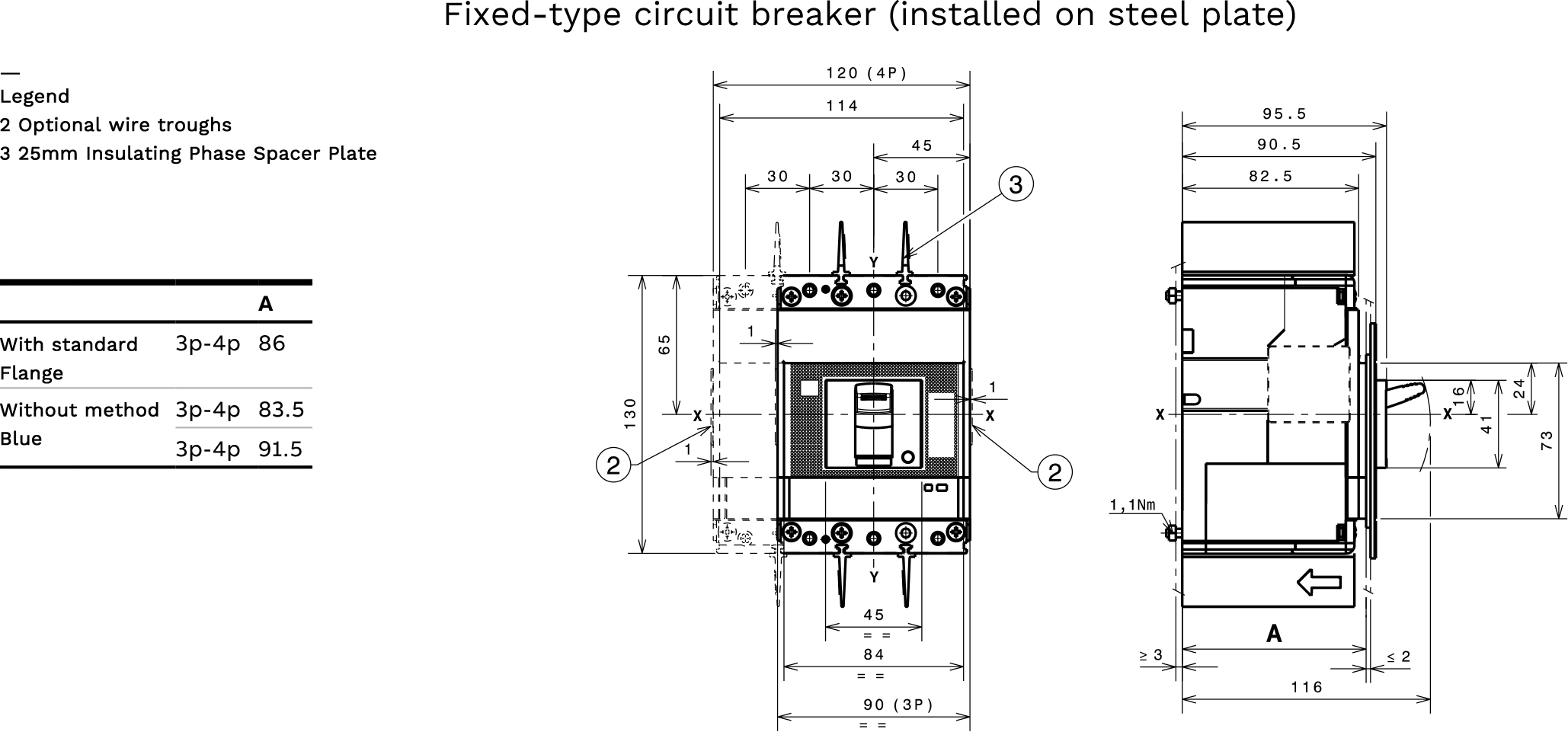
Dimensions
| Tmax XT2 - Installation |
| Installation of Fixed Circuit Breakers |
 |
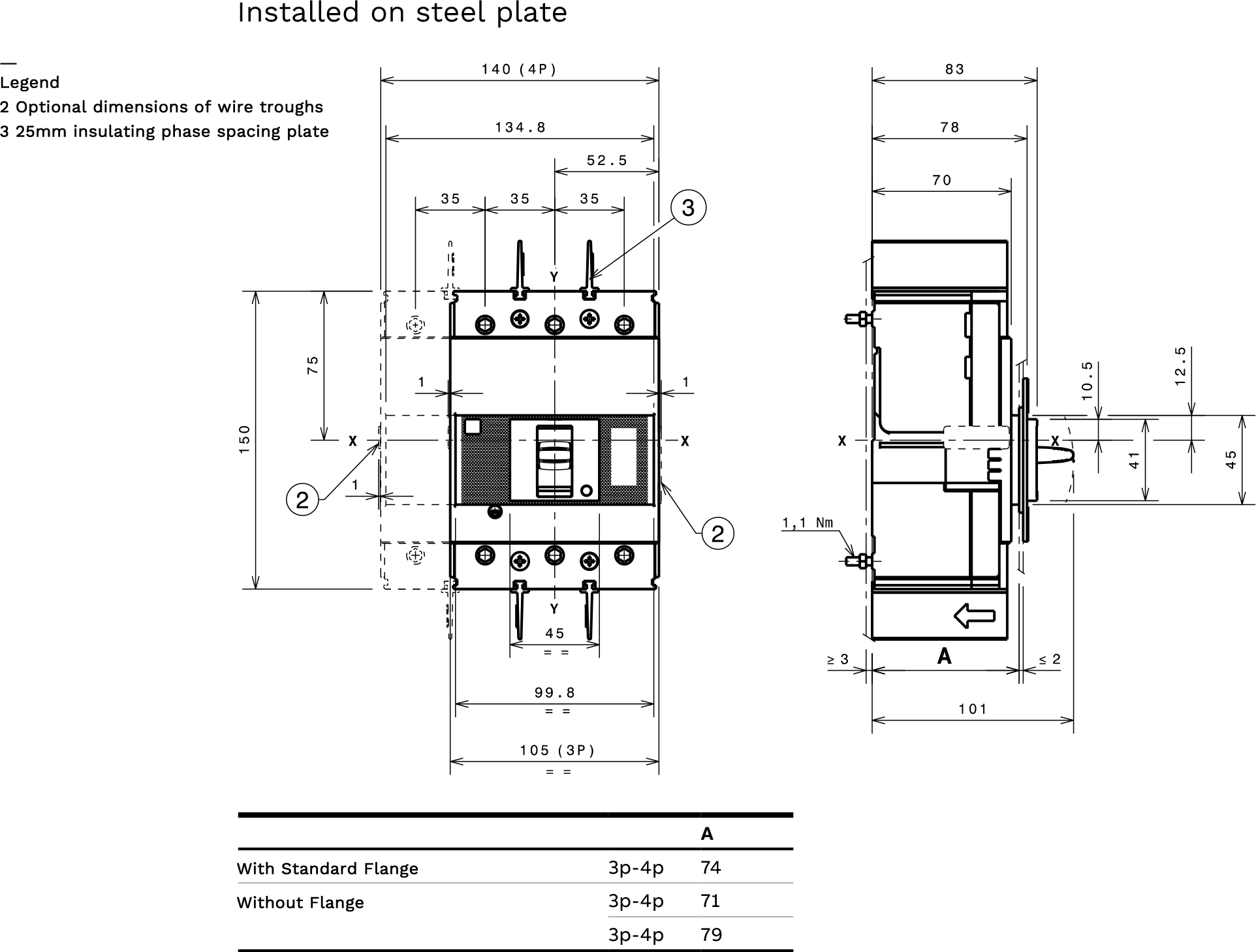
Dimensions
| Tmax XT3 - Installation |
| Installation of Fixed Circuit Breakers |
 |
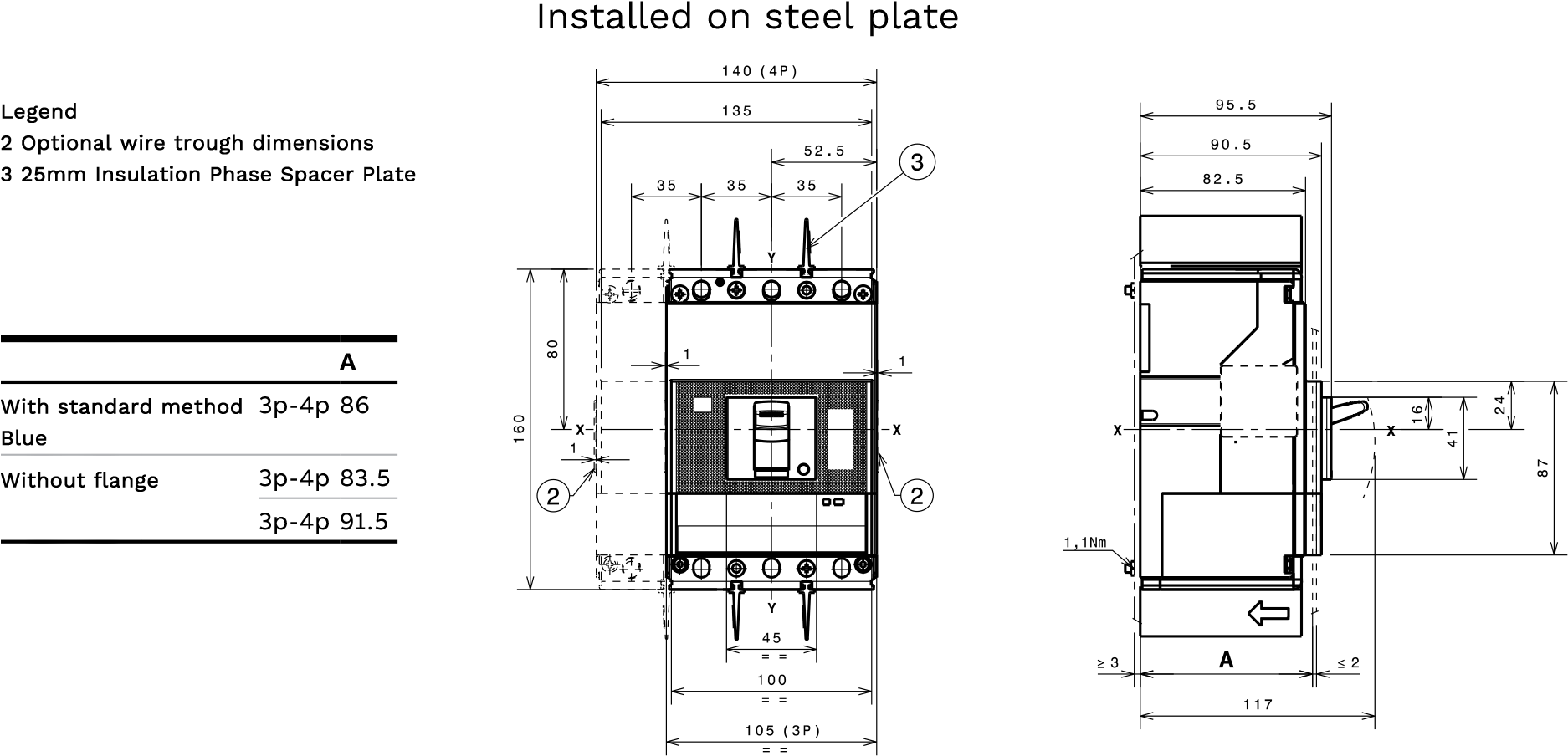
Dimensions
| Tmax XT4 - Installation |
| Installation of Fixed Circuit Breakers |
 |
Dimensions
| Tmax XT5 - Installation |
| Installation of Fixed Circuit Breakers |
 |
Dimensions
| Tmax XT6 - Installation |
| Installation of Fixed circuit breakers |
 |
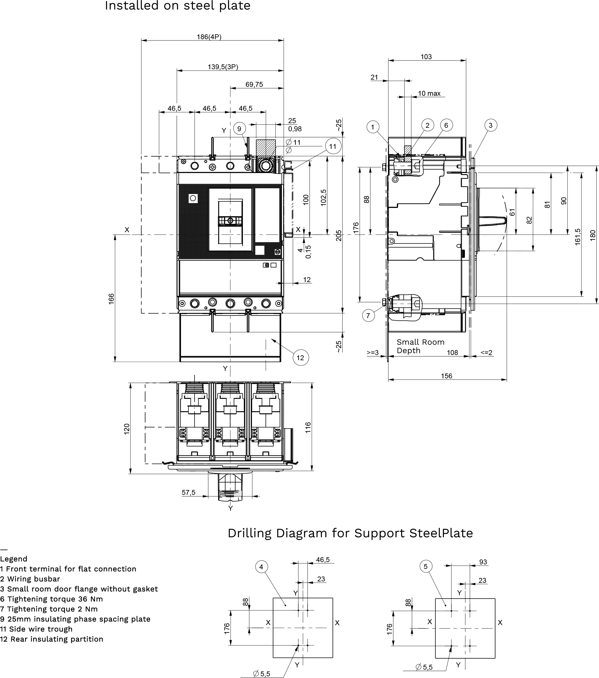
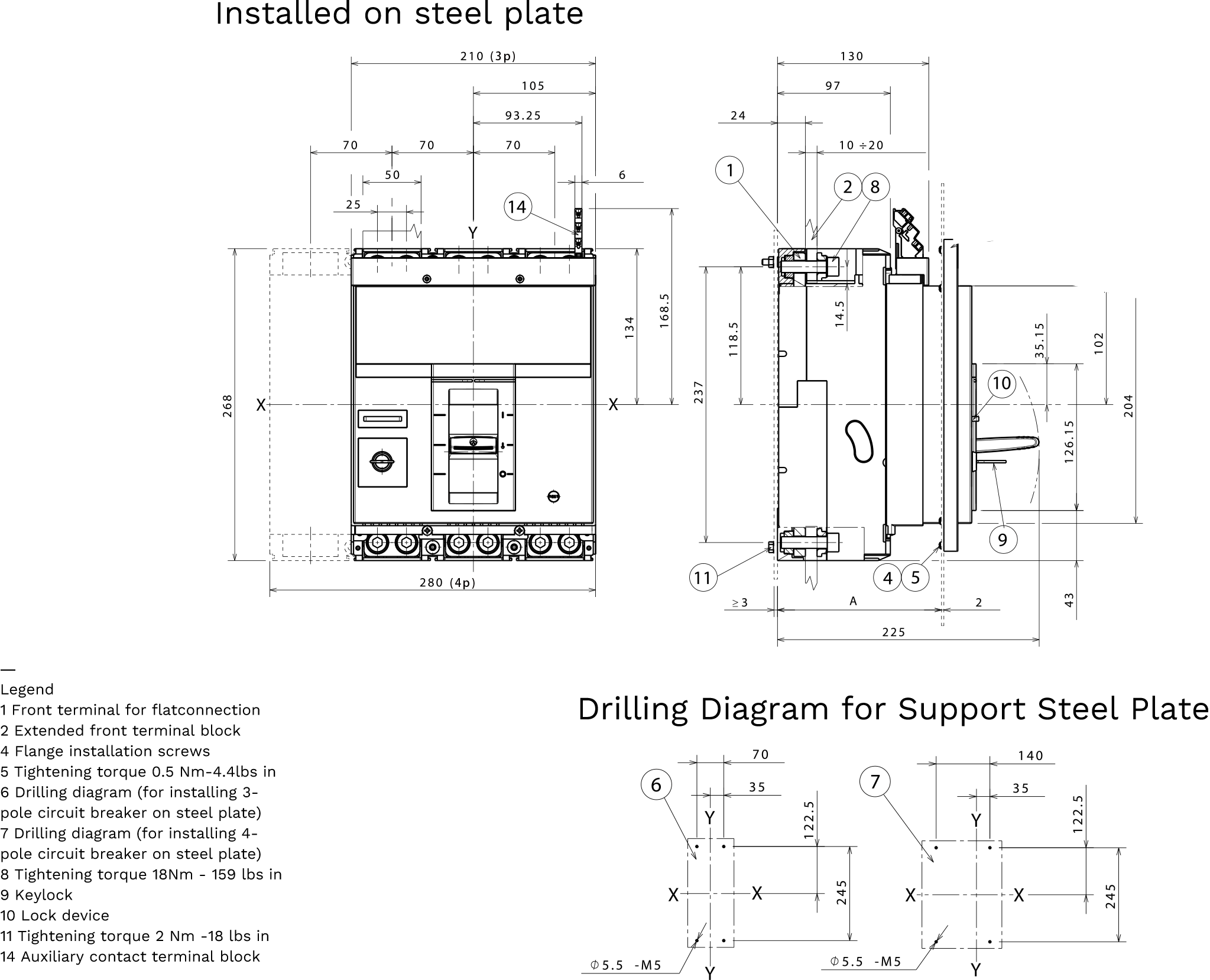
Dimensions
| Tmax XT7- Installation |
| Installation of Fixed Circuit Breakers |
 |
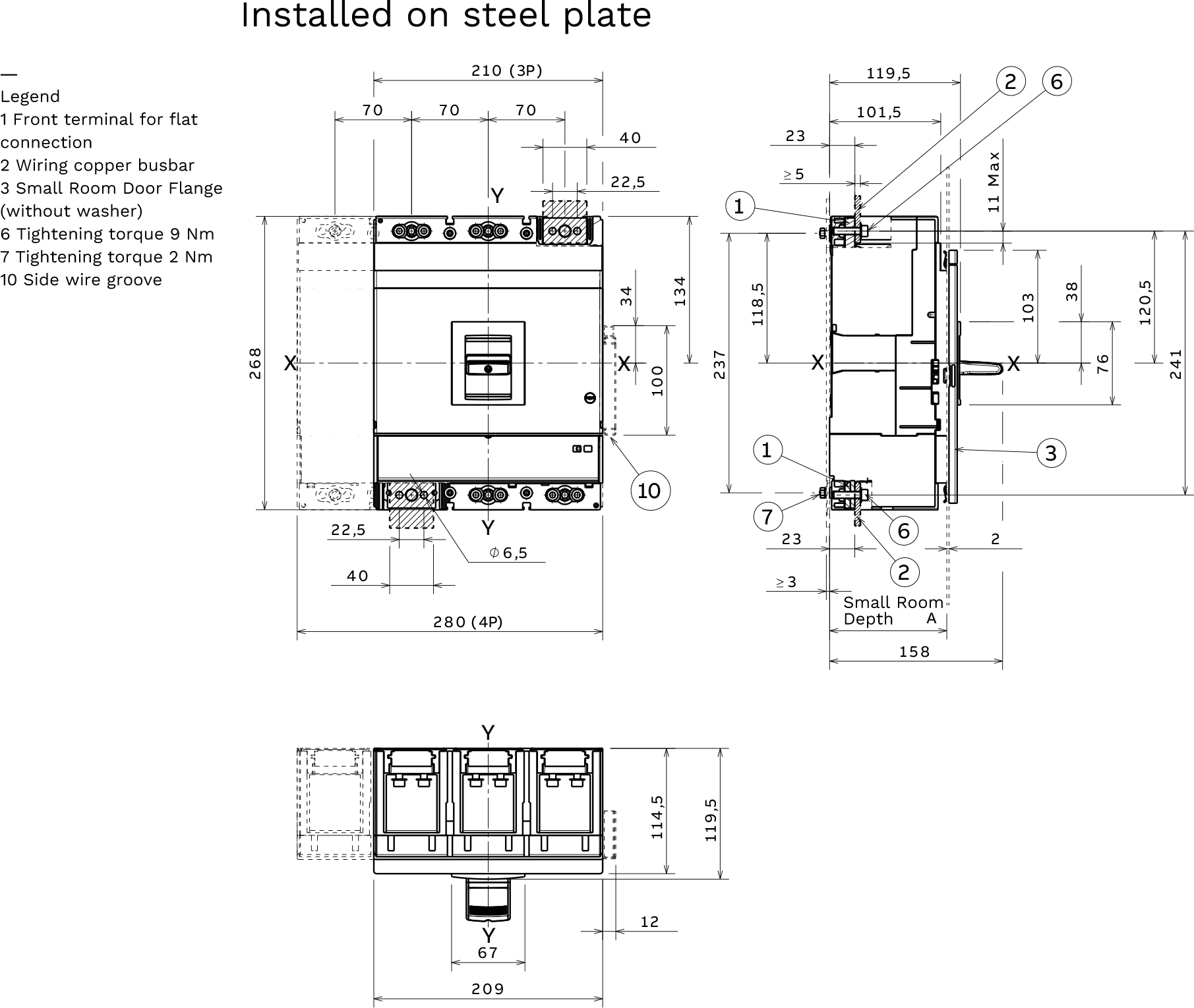
Dimensions
| Tmax XT7 M - Installation |
| Installation of Fixed Circuit Breakers |
 |
| Detailed breaking capacity parameters for XT1 - XT7 (based on IEC 60947-2 standard) | ||||||||||||
| Model | Frame current (A) | Division level code | 415V AC ultimate breaking capacity Icu (kA) | 690V AC ultimate breaking capacity Icu (kA) | Remark | |||||||
| XT1 | 160 | B | 18 | 3 | Standard power distribution for residential and commercial buildings | |||||||
| C | 25 | 4 | ||||||||||
| N | 36 | 6 | ||||||||||
| S | 50 | 8 | ||||||||||
| H | 70 | 10 | ||||||||||
| XT2 | 160 | N | 36 | 10 | High-performance models with a maximum breaking capacity of 200kA; support for various electronic trip units. | |||||||
| S | 50 | 12 | ||||||||||
| H | 70 | 15 | ||||||||||
| L | 120 | 18 | ||||||||||
| In | 150 | 20 | ||||||||||
| XT3 | 250 | N | 36 | 5 | 250A Class Industrial Standard Power Distribution | |||||||
| S | 50 | 6 | ||||||||||
| XT4 | 160 / 250 | N | 36 | 10 | 250A flagship model with integrated power metering function | |||||||
| H | 70 | 15 | ||||||||||
| XT5 | 400 / 630 | N | 36 | 20 | Filling the demand for 160A-400A | |||||||
| H | 70 | 22 | ||||||||||
| S | 50 | —— | ||||||||||
| XT6 | 630 / 800 | H | 70 | 25 | Suitable for high current distribution of 630A-800A | |||||||
| S | 50 | 30 | ||||||||||
| H | 70 | 42 | ||||||||||
| XT7 | 1000-1600 | S | 50 | 30 | The largest frame is used for main power distribution. | |||||||
| H | 70 | 42 | ||||||||||


| Trip Unit Types and Selection | ||||||||||||
| Trip unit type | Code | Protection function | Applicable models | Features | ||||||||
| Thermomagnetic | TMD | Overload long delay (L) + Short circuit instant (I) | XT1-XT4 | Adjustable thermal release, magnetic release for secure fastening | ||||||||
| Thermomagnetic | TMA | Overload long delay (L) + Short circuit instant (I) | XT1-XT5 | Both thermal and magnetic tripping are adjustable. | ||||||||
| Single magnet | MF/MA | Short circuit instantaneous protection | XT2-XT4 | Used for motor protection and contactor | ||||||||
| Electronic | Team I | Short circuit instant (I) | XT2/XT4 | Single-stage protection | ||||||||
| Electronic | Team LS/I | L + S + I three-stage protection | XT2/XT4/XT5/XT6 | Mode S provides selective protection. | ||||||||
| Electronic | LSI Team | L + S + I three-stage protection | XT2/XT4 | Complete three-segment protection | ||||||||
| Electronic | Team LSIG | L + S + I + G four-stage protection | XT2/XT4 | Includes ground fault protection | ||||||||
| Electricity metering | E-LSIG Team | L+S+I+G + Electrical Energy Measurement | XT4 | Integrated power metering function | ||||||||
| Motor protection | Ekip MI | Single magnetic protection | XT2 | Motor circuit short circuit protection | ||||||||
| Motor protection | Team M-LIU | Overload + Short circuit + Phase imbalance | XT2/XT4 | Motor Comprehensive Protection | ||||||||
| Motor protection | M-LRIU Team | Overload + stalled rotor + short circuit + phase imbalance | XT2/XT4 | Advanced motor protection | ||||||||
| Generator protection | Team G-LS/I | Three-stage protection | XT2/XT4 | Designed specifically for generator characteristics | ||||||||
| Neutral line protection | Team N-LS/I | Three-stage protection | XT2/XT4 | Suitable for high harmonic applications | ||||||||
Protection function descriptions:
● L (Long): Overload long-time delay protection
● S (Short): Short-circuit short-time delay protection (selective protection)
● I (Instantaneous): Short-circuit instantaneous protection
● G (Ground): Ground fault protection
Trip Unit Interchangeability
All models are available with either thermal-magnetic or electronic trip units, which are interchangeable. A solid green LED indicates normal operation, while a separate LED is dedicated to signaling abnormal protection conditions.
| Installation and Operation Method | ||||||||||||
| project | Optional type | |||||||||||
| Installation method | Fixed type, insertion type, pull-out type | |||||||||||
| Operation method | Toggle handle, rotary handle, extended rotary handle, electric operating mechanism | |||||||||||
| Incoming line method | Either top-in or bottom-in line is acceptable; no derating is required. | |||||||||||
| Installation location | It can be installed horizontally, vertically, or flat, without the need for derating. | |||||||||||